Macros tikz
Au cours de la rédaction de ma thèse j’ai été amené à
construire pas mal de figures, ce qui m’a conduit à
l’écriture de quelques macros tikz qui pourraient
reservir.
- Boîte exponentielle pour les réseaux de preuve.
La commande "Boite" prend 5 arguments :
- Coordonnée de la première porte
auxiliaire
- Coordonnée de la dernière porte
auxiliaire
- Coordonnée de la porte
principale
- Hauteur de la boîte
- Nom de la structure emboîtée
Par exemple, la figure suivante :
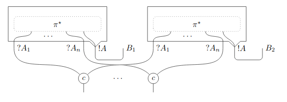
est obtenue avec Ce
code
\begin{tikzpicture}
	\coordinate(a1)at(0,0);
	\coordinate(an)at(3,0);
	\coordinate(a0)at(3.5,0);
	\draw[right](a1)node{$\wn A_1$};
	\draw[left](an)node{$\wn A_n$};
	\draw[right](a0)node{$\bg A$};
	\boite{(a1)}{(an)}{(a0)}{1.5}{$\pi^\star$}

	\coordinate(b1)at(6,0);
	\coordinate(bn)at(9,0);
	\coordinate(b0)at(9.5,0);
	\draw[right](b1)node{$\wn A_1$};
	\draw[left](bn)node{$\wn A_n$};
	\draw[right](b0)node{$\bg A$};
	\boite{(b1)}{(bn)}{(b0)}{1.5}{$\pi^\star$}

	\coordinate(t1)at($(a0)+(1.2,0)$);
	\coordinate(t2)at($(b0)+(1.2,0)$);
	\draw[right]($(t1)+(0,0)$)node{$B_1$};
	\draw[right]($(t2)+(0,0)$)node{$B_2$};
	\tcut{(a0)}{(t1)}{0.5}
	\tcut{(b0)}{(t2)}{0.5}

	\node[draw,cirle](c1)at($($0.5*($(a1)+(b1)$)$)+(0,-1.3)$){$c$};
	\node[draw,circle](cn)at($($0.5*($(an)+(bn)$)$)+(0,-1.3)$){$c$};

	\draw(a1)to[out=south,in=north west](c1);
	\draw(an)to[out=south,in=north west](cn);
	\draw[ultra thick,white](b1)to[out=south,in=north east](c1);
	\draw(b1)to[out=south,in=north east](c1);
	\draw(bn)to[out=south,in=north east](cn);

	\draw(c1)--++(0,-0.6);
	\draw(cn)--++(0,-0.6);
	\draw($0.5*($(c1)+(cn)$)$)node{$\cdots$};

\end{tikzpicture}
Le code de la macro est ici
\newcommand{\boite}[5]{%trois portes + hateur + nom
	%  BAS
	\coordinate(h)at($2/10*(0,#4)$);
	\coordinate(h')at($2/10*(h)$);
	\coordinate(p1)at($#1+(h)$);
	\coordinate(p2)at($#2+(h)$);
	\coordinate(p3)at($#3+(h')$);
	\draw#1--(p1);
	\draw#2--(p2);
	\draw#3--(p3);

	\coordinate(ag)at($(p2-|p3)$);
	\coordinate(ag')at($(p2)+(ag)$);
	\coordinate(ag'')at($1/2*(ag')$);%entre p2 et p3 à hauteur de p2
	\coordinate(ad)at($(ag)-(p2)$);
	\coordinate(ad')at($(ag)+(ad)$);%angle bas droit de la boîte
	\coordinate(ad'')at($(ag)+(ad')$);
	\coordinate(ad''')at($1/2*(ad'')$);%entre p3 et bord à hauteur du bord
	\coordinate(bg)at($(ad')-(ad''')$);
	\coordinate(bg')at($(p1)-(bg)$);%angle bas gauche
	\coordinate(hg)at($(bg')+(0,#4)$);%angle haut gauche
	\coordinate(hd)at($(ad')+(0,#4)$);%angle haut droite
	% Boîte
	\draw(bg')--(p1)--(p2)--(ag'')--(p3)--(ad''')--(ad');
	\draw(bg')--(hg)--(hd)--(ad');
	%INTERIEUR
	\coordinate(mh)at($(ad')-(ad''')$);%marge horizontale interne
	\coordinate(mv)at($1/3.5*(0,#4)$);%marge verticale interne
	\coordinate(mv-)at($(0,0)-(mv)$);%marge verticale interne neg
	\coordinate(mvh++)at($(mh)+(mv)$);% +/+
	\coordinate(mvh+-)at($(mh)-(mv)$);% +/-
	\coordinate(mvh-+)at($(mv)-(mh)$);% -/+
	\coordinate(mvh--)at($(0,0)-(mh)-(mv)$);%-/-
	\coordinate(pbg)at($(bg')+(mvh++)$);%bas gauche
	\coordinate(phg)at($(hg)+(mvh+-)$);%haut gauche
	\coordinate(phd)at($(hd)+(mvh--)$);%haut droite
	\coordinate(pbd)at($(ad')+(mvh-+)$);%bas droite
	\draw[fil, dotted](pbg)--(phg)--(phd)--(pbd)--cycle;%réseau
	%FILS INTERIEURS
	\coordinate(p''')at($(pbd)-(pbg)$);
	\coordinate(p1'')at($1/5*(p''')$);
	\coordinate(p1')at($(pbg)+(p1'')$);
	\coordinate(p2'')at($3/5*(p''')$);
	\coordinate(p2')at($(pbg)+(p2'')$);
	\coordinate(p3'')at($4/5*(p''')$);
	\coordinate(p3')at($(pbg)+(p3'')$);
	\draw[draw,rounded corners](p1')to[out=south,in=north](p1);
	\draw[draw,rounded corners](p2')to[out=south,in=north](p2);
	\draw[draw,rounded corners](p3')to[out=south,in=north](p3);
	\coordinate(dot')at($2/5*(p''')$);
	\coordinate(mv'-)at($1/2*(mv-)$);
	\draw($(pbg)+(dot')+(mv'-)$)node{$\cdots$};%points suspension
	%NOM
	\coordinate(mil')at($(bg')+(hd)$);
	\coordinate(mil)at($1/2*(mil')$);
	\draw(mil)node{#5};
}
- Complexe de protocole de dimension deux
(subdivision chromatique du 2-simplexe itérée
1, 2 et 3 fois).
- La macro
\Complexe
prend 4 argumentts. Les coordonnées des trois
sommets du 2-simplexe. Puis le style de trait.
Par exemple, la figure suivante :
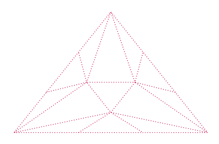
est obtenue avec Ce
code
\begin{tikzpicture}

	\coordinate(1)at(0,0);
	\coordinate(2)at(8,0);
	\coordinate(3)at(4,5);

	\Complexe{(1)}{(2)}{(3)}{thick,dotted,purple}

\end{tikzpicture}
- La macro
\ComplexeItere
prend 5 argumentts. Les coordonnées des trois
sommets du 2-simplexe,le style de trait
de la première subdivision, puis le
style de trait de la seconde
(attention, la deuxième subdivision
est tracée par-dessus la première)
Par exemple, la figure suivante :
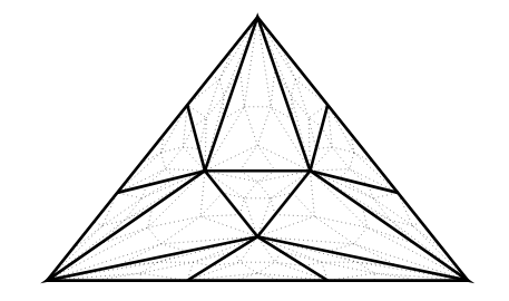
est obtenue avec Ce
code
\begin{tikzpicture}

	\coordinate(1)at(0,0);
	\coordinate(2)at(8,0);
	\coordinate(3)at(4,5);

	\ComplexeItere{(1)}{(2)}{(3)}{ultra thick}{dotted}

\end{tikzpicture}
- La macro
\ComplexeItereiD
prend argumentts. Les coordonnées des trois
sommets du 2-simplexe, puis les style
de traits des première, deuxième et
troisième subdivision.
Par exemple, la figure suivante :
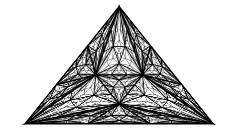
est obtenue avec Ce
code
\begin{tikzpicture}
	\coordinate(1)at(0,0);
	\coordinate(2)at(8,0);
	\coordinate(3)at(4,5);

	\ComplexeItereD{(1)}{(2)}{(3)}{ultra thick}{thick}{}
\end{tikzpicture}
- Un dernier exemple, la figure :
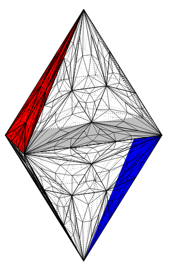
est obtenue avec Ce
code
\begin{tikzpicture}

	\coordinate(q1)at(0,0);
	\coordinate(q2)at(2.5,0);
	\coordinate(q3)at($(q1)+(0.3,-0.3)$);
	\coordinate(q4)at($(q2)+(-0.3,0.3)$);
	\coordinate(q5)at($(q1)+($1/2*($(q1)+(q2)$)$)+(0,2)$);
	\coordinate(q6)at($(q1)+($1/2*($(q1)+(q2)$)$)+(0,-2)$);

	\draw(q1)--(q5)--(q3)--(q1)--(q6)--(q3)--(q2)--(q5);
	\draw(q2)--(q6);

	\draw[gray,dotted](q1)--(q4)--(q2);
	\draw[gray,dotted](q5)--(q4)--(q6);

	\ComplexeItere{(q1)}{(q4)}{(q5)}{dotted}{dotted}
	\ComplexeItere{(q1)}{(q4)}{(q6)}{dotted}{dotted}
	\ComplexeItere{(q2)}{(q4)}{(q5)}{dotted}{dotted}

	\fill[color=blue](q2)--(q4)--(q6);
	\ComplexeItere{(q2)}{(q4)}{(q6)}{dotted}{dotted}
	\fill[color=lightgray](q1)--(q3)--(q2)--(q4);
	\fill[color=red](q1)--(q3)--(q5);

	\ComplexeItere{(q1)}{(q3)}{(q5)}{}{}
	\ComplexeItere{(q1)}{(q3)}{(q6)}{}{}
	\ComplexeItere{(q2)}{(q3)}{(q5)}{}{}
	\ComplexeItere{(q2)}{(q3)}{(q6)}{}{}

\end{tikzpicture}
- Les macros sont Ici
\newcommand{\Complexe}[4]{%sommets+style
	%%% ATTENTION
	%% NE PAS UTILISER (vi) EN APPLEANT LA MACRO
	\coordinate(v1)at #1;
	\coordinate(v2)at #2;
	\coordinate(v3)at #3;
	%segment bas
	\coordinate(v12-1)at($(v1)+($1/3*($(v2)-(v1)$)$)$);%point au premier tiers
	\coordinate(v12-2)at($(v1)+($2/3*($(v2)-(v1)$)$)$);%point au deuxième tiers
	%segment gauche
	\coordinate(v13-1)at($(v1)+($1/3*($(v3)-(v1)$)$)$);%point au premier tiers
	\coordinate(v13-2)at($(v1)+($2/3*($(v3)-(v1)$)$)$);%point au premier tiers
	%segment droit
	\coordinate(v23-1)at($(v2)+($1/3*($(v3)-(v2)$)$)$);%point au premier tiers
	\coordinate(v23-2)at($(v2)+($2/3*($(v3)-(v2)$)$)$);%point au premier tiers
	%Mi-chemins
	\coordinate(v12)at($(v1)+($1/2*($(v2)-(v1)$)$)$);
	\coordinate(v13)at($(v1)+($1/2*($(v3)-(v1)$)$)$);
	\coordinate(v23)at($(v2)+($1/2*($(v3)-(v2)$)$)$);
	%Tiers des Médianes
	\coordinate(v23-v1)at($(v1)+($5/6*($(v23)-(v1)$)$)$);%interne gauche
	\coordinate(v13-v2)at($(v2)+($5/6*($(v13)-(v2)$)$)$);%interne droit
	\coordinate(v12-v3)at($(v3)+($5/6*($(v12)-(v3)$)$)$);%interne bas
	%Tracé
	\draw[#4](v1)--(v2)--(v3)--cycle;
	\draw[#4](v12-v3)--(v23-v1)--(v13-v2)--cycle;
	\draw[#4](v1)--(v13-v2)--(v3)--(v23-v1)--(v2)--(v12-v3)--cycle;
	\draw[#4](v12-1)--(v12-v3)--(v12-2);
	\draw[#4](v23-1)--(v23-v1)--(v23-2);
	\draw[#4](v13-1)--(v13-v2)--(v13-2);
}
\newcommand{\ComplexeItere}[5]{%sommets + style1 + style2
	%%%%%%% ATTENTION
	% NE PAS UTILISER (ri) ni (vi) EN APPELANT LA MACRO
	%%%
	\coordinate(r1)at #1;
	\coordinate(r2)at #2;
	\coordinate(r3)at #3;

	%segment bas
	\coordinate(r12-1)at($(r1)+($1/3*($(r2)-(r1)$)$)$);%point au premier tiers
	\coordinate(r12-2)at($(r1)+($2/3*($(r2)-(r1)$)$)$);%point au deuxième tiers
	%segment gauche
	\coordinate(r13-1)at($(r1)+($1/3*($(r3)-(r1)$)$)$);%point au premier tiers
	\coordinate(r13-2)at($(r1)+($2/3*($(r3)-(r1)$)$)$);%point au premier tiers
	%segment droit
	\coordinate(r23-1)at($(r2)+($1/3*($(r3)-(r2)$)$)$);%point au premier tiers
	\coordinate(r23-2)at($(r2)+($2/3*($(r3)-(r2)$)$)$);%point au premier tiers
	%Mi-chemins
	\coordinate(r12)at($(r1)+($1/2*($(r2)-(r1)$)$)$);
	\coordinate(r13)at($(r1)+($1/2*($(r3)-(r1)$)$)$);
	\coordinate(r23)at($(r2)+($1/2*($(r3)-(r2)$)$)$);
	%Tiers des Médianes
	\coordinate(r23-r1)at($(r1)+($5/6*($(r23)-(r1)$)$)$);%interne gauche
	\coordinate(r13-r2)at($(r2)+($5/6*($(r13)-(r2)$)$)$);%interne droit
	\coordinate(r12-r3)at($(r3)+($5/6*($(r12)-(r3)$)$)$);%interne bas

	%Tracé Premier complexe
	\draw[#4](r1)--(r2)--(r3)--cycle;
	%\draw(v12)--(v23)--(v13)--cycle;
	\draw[#4](r12-r3)--(r23-r1)--(r13-r2)--cycle;
	\draw[#4](r1)--(r13-r2)--(r3)--(r23-r1)--(r2)--(r12-r3)--cycle;
	\draw[#4](r12-1)--(r12-r3)--(r12-2);
	\draw[#4](r23-1)--(r23-r1)--(r23-2);
	\draw[#4](r13-1)--(r13-r2)--(r13-2);
	%Tracé deuxième subdivision
	\Complexe{(r12-1)}{(r12-2)}{(r12-r3)}{#5}
	\Complexe{(r1)}{(r12-1)}{(r12-r3)}{#5}
	\Complexe{(r2)}{(r12-2)}{(r12-r3)}{#5}

	\Complexe{(r13-1)}{(r13-2)}{(r13-r2)}{#5}
	\Complexe{(r1)}{(r13-1)}{(r13-r2)}{#5}
	\Complexe{(r3)}{(r13-2)}{(r13-r2)}{#5}

	\Complexe{(r23-1)}{(r23-2)}{(r23-r1)}{#5}
	\Complexe{(r2)}{(r23-1)}{(r23-r1)}{#5}
	\Complexe{(r3)}{(r23-2)}{(r23-r1)}{#5}

	\Complexe{(r1)}{(r13-r2)}{(r12-r3)}{#5}
	\Complexe{(r2)}{(r12-r3)}{(r23-r1)}{#5}
	\Complexe{(r3)}{(r13-r2)}{(r23-r1)}{#5}

	\Complexe{(r12-r3)}{(r23-r1)}{(r13-r2)}{#5}
}
\newcommand{\ComplexeItereD}[6]{%sommets + style1 + style2 + style3
	%%%%%%% ATTENTION
	% NE PAS UTILISER (ri) ni (vi) EN APPELANT LA MACRO
	%%%
	\coordinate(t1)at #1;
	\coordinate(t2)at #2;
	\coordinate(t3)at #3;

	%segment bas
	\coordinate(t12-1)at($(t1)+($1/3*($(t2)-(t1)$)$)$);%point au premier tiers
	\coordinate(t12-2)at($(t1)+($2/3*($(t2)-(t1)$)$)$);%point au deuxième tiers
	%segment gauche
	\coordinate(t13-1)at($(t1)+($1/3*($(t3)-(t1)$)$)$);%point au premier tiers
	\coordinate(t13-2)at($(t1)+($2/3*($(t3)-(t1)$)$)$);%point au premier tiers
	%segment droit
	\coordinate(t23-1)at($(t2)+($1/3*($(t3)-(t2)$)$)$);%point au premier tiers
	\coordinate(t23-2)at($(t2)+($2/3*($(t3)-(t2)$)$)$);%point au premier tiers
	%Mi-chemins
	\coordinate(t12)at($(t1)+($1/2*($(t2)-(t1)$)$)$);
	\coordinate(t13)at($(t1)+($1/2*($(t3)-(t1)$)$)$);
	\coordinate(t23)at($(t2)+($1/2*($(t3)-(t2)$)$)$);
	%Tiers des Médianes
	\coordinate(t23-t1)at($(t1)+($5/6*($(t23)-(t1)$)$)$);%interne gauche
	\coordinate(t13-t2)at($(t2)+($5/6*($(t13)-(t2)$)$)$);%interne droit
	\coordinate(t12-t3)at($(t3)+($5/6*($(t12)-(t3)$)$)$);%interne bas

	%Tracé Premier complexe
	\draw[#4](t1)--(t2)--(t3)--cycle;
	%\draw(v12)--(v23)--(v13)--cycle;
	\draw[#4](t12-t3)--(t23-t1)--(t13-t2)--cycle;
	\draw[#4](t1)--(t13-t2)--(t3)--(t23-t1)--(t2)--(t12-t3)--cycle;
	\draw[#4](t12-1)--(t12-t3)--(t12-2);
	\draw[#4](t23-1)--(t23-t1)--(t23-2);
	\draw[#4](t13-1)--(t13-t2)--(t13-2);
	%Tracé deuxième subdivision
	\ComplexeItere{(t12-1)}{(t12-2)}{(t12-t3)}{#5}{#6}
	\ComplexeItere{(t1)}{(t12-1)}{(t12-t3)}{#5}{#6}
	\ComplexeItere{(t2)}{(t12-2)}{(t12-t3)}{#5}{#6}

	\ComplexeItere{(t13-1)}{(t13-2)}{(t13-t2)}{#5}{#6}
	\ComplexeItere{(t1)}{(t13-1)}{(t13-t2)}{#5}{#6}
	\ComplexeItere{(t3)}{(t13-2)}{(t13-t2)}{#5}{#6}

	\ComplexeItere{(t23-1)}{(t23-2)}{(t23-t1)}{#5}{#6}
	\ComplexeItere{(t2)}{(t23-1)}{(t23-t1)}{#5}{#6}
	\ComplexeItere{(t3)}{(t23-2)}{(t23-t1)}{#5}{#6}

	\ComplexeItere{(t1)}{(t13-t2)}{(t12-t3)}{#5}{#6}
	\ComplexeItere{(t2)}{(t12-t3)}{(t23-t1)}{#5}{#6}
	\ComplexeItere{(t3)}{(t13-t2)}{(t23-t1)}{#5}{#6}

	\ComplexeItere{(t12-t3)}{(t23-t1)}{(t13-t2)}{#5}{#6}
}

